
Flight Software design for INSPIRE-0 PS4-OP Payload
My project involved designing a payload for the PSLV 4th Stage Orbital Platform (PS4-OP), which is a platform created by repurposing the spent fourth/final stage of the Polar Satellite Launch Vehicle (PSLV)), to conduct in-orbit scientific experiments. The payload aims to demonstrate that, accurate Solar Spectral Irradiance measurements are possible using new miniaturized and robust disruptive instruments.
I first developed the system architecture of the payload including the interfaces between the various subsystems, namely, the PS4-OP adapter board, OBC, EPS, and the AS7265x spectral sensor. I then designed the schematic and layout (using KiCAD) of the PS4-OP adapter board and performed unit tests on all the subsystem PCBs. My major contribution was in developing the flight software for the OBC using C and implementing it on the ARM CortexM3 microprocessor of the SmartFusion2 SoC FPGA. I developed a bare-metal schedular to perform the sequence of operations and designed modular subsystem libraries, to allow reconfigurability for future missions. Lastly, I conducted comprehensive performance tests and thermal-vacuum environmental test on the payload, and developed a decoder application using Python to analyze level-0 and level-1 payload telemetry. After the successful completion of these tests, the payload was delivered for a planned launch in 2021. 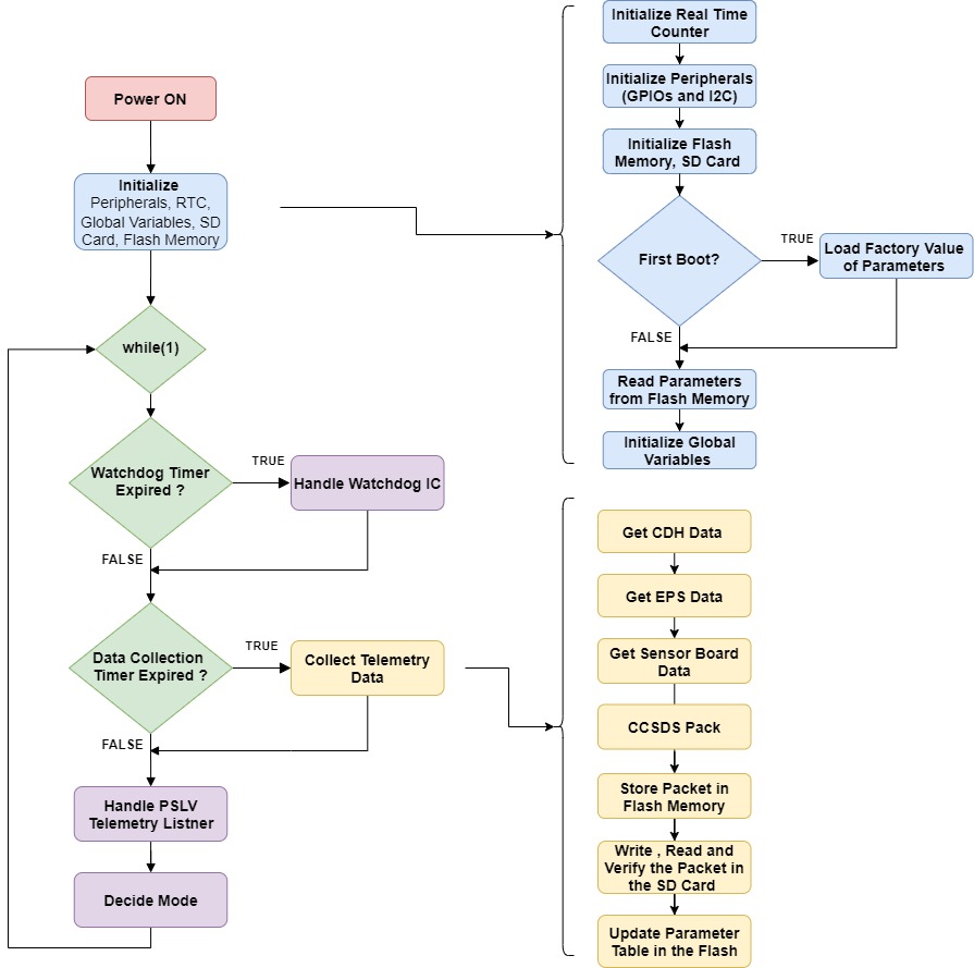
The flight software for IS0 is written in C as a sequential program. The C code runs on the ARM CortexM3 Micro-controller implemented in the Microsemi SmartFusion2 SoC(System on Chip) FPGA. The FPGA implements interfaces with the PicoSIM sensor board and the EPS board. Apart from the peripherals for interfacing, custom developed verilogIP cores are also implemented in the FPGA, including aWatchdog Timer Handler, a Real Time Counter and a LaunchVehicle Telemetry Handler. The flowchart shown in figure summarizes the entire flight software sequence of operationsof the payload.Immediately after power ON the initialization proceduretakes place. This includes initialization of the various mem-ories, peripheral drivers, software parameters and variables.After this the program enters into an infinite while loop wherethe the tasks are carried out sequentially. First the externalwatchdog peripheral is handled, this is done by “petting” the watchdog timer handler Verilog IP core with toggle signalevery 1 second. This watchdog timer is used to generate a resetto the C&DH in case the flight software doesn’t generate thetoggle signal timely. Next the data from the C&DH (Commandand Data Handling Board), the EPS (Electrical Power System) and the PicoSIM sensor board is collected using differentperipherals. Then this data is converted it into the CCSDSbeacon packet format and stored in the non-volatile flashmemory of the SoM. The data packet is stored in the SDcard and also read back from it to verify the working of theSD card. Once the data packet is formed, it is copied to thelaunch vehicle telemetry handler verilog core implemented inthe FPGA. The telemetry handler then sends the data packetto the launch vehicle when commanded